Overview
After many deployments, reading most of Cisco’s documentation, best practices, deployment guides, and after 150+ hours creating a tool to automate the deployment of Cisco 9800 Wireless Controllers to share with my team, I am sharing my thoughts about how these controllers *should* be configured. It should be mentioned that I use the GUI as little as possible.
I first sought to understand the differences between the configuration models, the use of profiles and tags. While understanding the need for flexibility and hearing my customers repeatedly complain about the impact that simple changes within Cisco’s AireOS controllers could result in, I have been deploying 9800s with the maximum amount of flexibility possible. The simple truth is that, I don’t know when and where a customer is going to need to change settings. Will the setting they change be in a policy profile, an RF profile, AP join profile? How widespread would the change be? If the customer does not understand the configuration model of the controller, will they make a change that impacts more areas than they intended to? The problem is that these questions are likely being asked during a time when the customer is dealing with an issue, potentially just at a single location, and is seeking to resolve it by making configuration changes. Thankfully, this can all be avoided by carefully mapping out your profiles and tags.
Profile and Tag Review
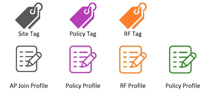
To start, we’ll quickly review the configuration model of the 9800 controllers. Be sure to review this document published by Cisco. The image below shows the basics of AP tags and profiles. The link above also includes a list of all settings and which profile they are configured in.

Be sure to also view this link to understand the affect of roaming between policy profiles if you are configuring multiple “sites” within the same location where you expect clients to seamlessly roam between APs tagged with different site tags. This page has a list of configurations that can vary from one policy profile to the next and still allow seamless roaming between the two. The “wireless client vlan-persistent” is used to ‘Enable client roaming across different policy profiles’.

I use the following icons to identify profiles and tags. Each color represents a different type. In the spirit of Halloween, I will the icons below to represent each type.
Location-based Tagging
If you aren’t already aware, using location-based tagging is the only method you should be using. I use this method exclusively, therefor I won’t use any visuals to show that tags are applied to APs. Rather, I show that tags are applied to a physical location where APs are installed.

Basic Configuration
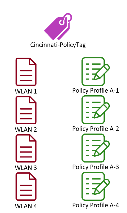
In this example, we’ll assume the wireless controller(s) will be in the Cincinnati office with all APs in local mode. This means that we won’t be using any Flex Profiles. A simple, not flexible, way to configure this controller with 4 SSIDs would look something like the layout below.

Flexible Configuration
As shown above, the same policy profile is tied to each WLAN. Any change that needs to be made to “Policy Profile A” will now affect all WLANs. This includes settings such as DHCP server, QoS, and timeout settings. Previously, with AireOS controllers, these settings were found within the “Advanced” tab of the WLAN. Even if for this reason alone, it should be clear that a separate policy profile should be created for each WLAN. This might not seem so bad considering that all these settings are still tied to a single physical location and, in the case of an issue arising, we would still only affect this location with any changes that are made but we still want to avoid making a change to all WLANs. This may seem like an excess of work if you are used to using the GUI to configure your controllers. The truth is, you can simply configure one profile, gather the lines of config from the CLI, then copy, change the names, and paste. Even if they all have the same configuration, you now have the flexibility to make changes to a single profile that will only impact a single WLAN. See the table below.
Let’s consider an additional office in Columbus, Ohio. There are a few ways to configure when dealing with multiple locations. See the list below that shows options and the scale of the impact:
- Repurpose all profiles and tags used at the Cincinnati office.
- Changes to profiles would affect all APs at each location and all WLANs

- Create a new Policy Tag but repurpose “Policy Profile A”
- Same as above. Changes to profiles would affect all APs at each location and all WLANs

- Create a new policy tag and new policy profile (“Policy Profile B”), then apply to all WLANs in the new office.
- This puts us back in the boat where a single policy profile is used for all WLANs. Any changes to “Policy Profile B” would affect all WLANs in the Columbus office.

- Create a new policy tag and new policy profiles (“Policy Profile B[1-4]”), then apply each unique policy profile to a unique WLAN.

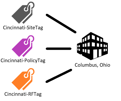
Policy profiles and tags aren’t the only area of configuration where this same logic can and should be applied. Each location will also be tagged with a site tag and RF tag. We’ll start by discussing the easier of the two, RF profiles and tags.
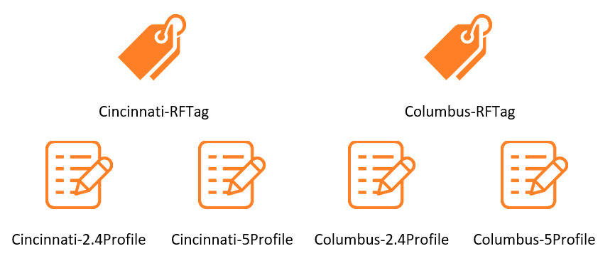
RF tags include an RF profile for both the 2.4 and 5GHz bands. As shown in our location and tag mapping below, we have an RF Tag named “Cincinnati-RFTag. This tag applies the RF profiles “Cincinnati-2.4Profile” and “Cincinnati 5Profile” that control the RF settings on the APs at the location in which the tag is applied.

Each location should be tagged with a unique RF Tag that has unique RF profiles. For simplicity, I always name my RF profiles for the site in which they are applied. If RF profiles are repurposed from one site to the next, a configuration change to either the 2.4 or 5GHz profile will affect both locations. If you aren’t familiar with the settings located within RF profiles, they include channel selection, transmit power, data rates, channel bonding, and many others. Following our example of two offices, the RF tags and profiles should be configured as such:
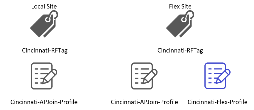
The last of the profiles that are applied to locations via site tags are AP join profiles and Flex profiles. The primary difference between “local” sites and Flex sites are that Flex sites include a Flex profile in the site tag. See the image below.
Like RF Profiles, it is best to create a unique AP Join profile for each site. The settings found within the AP join profiles include AP admin username and password, CDP, MTU, and CAPWAP settings amongst many others. Although these settings are likely to match across an entire organization, I do know of multiple troubleshooting scenarios where an adjustment to the MTU was necessary.
Flex profiles are similar in that there should be a unique Flex profile for each site; they include settings such as native VLAN, local authentication settings, VLAN to name mapping, and more. Larger organizations with many remote sites may find it easier to repurpose Flex profiles when the same VLANs are used at every site. Regardless, to employ the maximum amount of flexibility, a unique profile should be created for each.
Configuration
In the sections below, you can find the CLI commands for each profile and tag type. As mentioned earlier, these can be copied/pasted once you have a baseline configuration that you know will be included in each profile. Be sure to adjust the settings to values that your environment requires!
Create a WLAN
wlan “WLAN1” 1 “WLAN1”
security wpa wpa2
security wpa psk set-key ascii 0 NeVeRgUe$$
security wpa wpa2 ciphers aes
no security wpa akm dot1x
security wpa akm psk
broadcast-ssid
band-select
no load-balance
no peer-blocking
assisted-roaming neighbor-list
no security ft
no shutdown
Create a Policy Profile
wireless profile policy “Cincinnati-PolicyProfile-1”
description “Cincinnati Policy Profile for WLAN1”
ipv4 dhcp server 192.168.1.1
vlan 1
no shutdown
exit
Create 5GHz RF Profile
ap dot11 5ghz rf-profile Cincinnati-5Profile
description “5GHz RF Profile for Cincinnati”
channel chan-width 20
rate RATE_24M Supported
rate RATE_36M Supported
rate RATE_48M Supported
rate RATE_54M Supported
channel remove 100
channel remove 104
channel remove 108
channel remove 112
channel remove 116
channel remove 120
channel remove 124
channel remove 128
channel remove 132
channel remove 136
channel remove 140
channel remove 144
tx-power min 11
tx-power min 17
no shutdown
exit
Create 2.4GHz RF Profile
ap dot11 24ghz rf-profile Cincinnati-2.4Profile
description “2.4GHz RF Profile for Cincinnati”
tx-power min 11
tx-power max 17
rate RATE_1M disable
rate RATE_2M disable
rate RATE_5_5M disable
rate RATE_6M disable
rate RATE_9M disable
rate RATE_11M disable
rate RATE_12M mandatory
rate RATE_18M supported
rate RATE_24M supported
rate RATE_36M supported
rate RATE_48M supported
rate RATE_54M supported
no shutdown exit
Create an AP Join Profile
ap profile Cincinnati-APJoinProfile
mgmtuser username Admin password 0 Temp456$%^ secret 0 Temp456$%^
ssh
no telnet
exit
Create a Flex Profile
wireless profile flex Cincinnati_FlexProfile
description “Cincinnati Flex Profile”
local-auth ap peap
native-vlan-id 50
vlan-name IOT
vlan-id 4
vlan-name BYOD
vlan-id 3
vlan-name Corp
vlan-id 50
vlan-name Guest
vlan-id 2
exit
Create a Policy Tag
wireless tag policy Cincinnati-PolicyTag
wlan “WLAN1” policy “Cincinnati-PolicyProfile-1”
wlan “WLAN2” policy “Cincinnati-PolicyProfile-2”
wlan “WLAN3” policy “Cincinnati-PolicyProfile-3”
wlan “WLAN4” policy “Cincinnati-PolicyProfile-4”
exit
Create an RF Tag
wireless tag rf Cincinnati_RFTag
description “RF Tag for Cincinnati”
24ghz-rf-policy Cincinnati-2.4Profile
5ghz-rf-policy Cincinnati-5Profile
exit
Create a Site Tag
wireless tag site Cincinnati_SiteTag
ap-profile Cincinnati-APJoinProfile
description “Local site tag for Cincinnati”
exit
Location-based tagging
ap location name Cincinnati
description “AP Location for Cincinnati”
tag policy Cincinnati_PolicyTag
tag rf Cincinnati_RFTag
tag site Cincinnati_SiteTag
exit
Add AP(s) to the created location
ap location name Cincinnati
ap-eth-mac aaaa.bbbb.cccc
ap-eth-mac aaaa.bbbb.cccc
ap-eth-mac aaaa.bbbb.cccc
Conclusion
I hope this post has been helpful in both your understanding of how to configure profiles and tags but how to do so in a way that will provide the most flexibility to reduce the impact of changes in the environment. Stay tuned for more 9800 deployment-related posts!
References
Understand Catalyst 9800 Wireless Configuration Model

Leave a comment