Overview
IOS-XE 17.1.X brought the concept of the redundancy management interface to the Cisco 9800 wireless controllers that we know from AireOS. Previously, connecting controllers back-to-back via their RPs was fool proof; this is still an option on the 9800s but is no longer best practice. This guide expects the use of IOS-XE 17.1.X or later and assumes you are pairing new controllers out of the box with no prior configuration. If you are adding a second controller to one that is in production, be sure to understand the requirements fully.

Tips and Tricks
To start, there are a few things I’ve started to do recently that have helped tremendously.
Tip #1 – Console Into Both Controllers Simultaneously
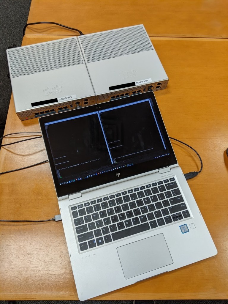
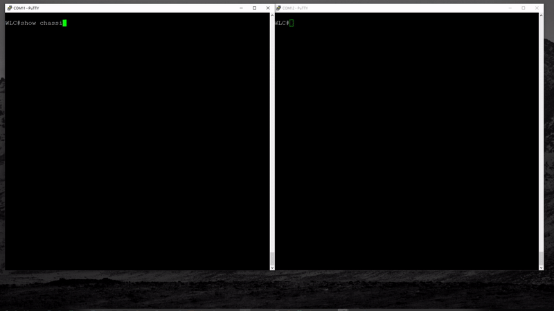
Connecting to both controllers is easy when you have more than one console or micro-USB cable. I always carry multiple USB cables not only because they get torn up easily, but also because I always have my Ekahau Sidekick and WLAN Pi on me. Both use a micro-USB cable (I leave the bolts out of my WLAN Pi for easy access to the cable when I need it). I set the controllers side-by-side, open two sessions, and position the putty windows accordingly.
Tip #2 – Configure HA with Controllers “Offline”
Issue the commands on each controller before they touch the network. Although the HA “state” will change immediately when the controllers can see each other, I found it best to apply the configuration and allow them to find each other while booting up. More on this later.
Tip #3 – Validate Your Network Configuration
Although obvious, this can cause a lot of confusion and frustration. There is a table in Cisco’s documentation that describes active/standby-recovery states when the gateway cannot be reached but the controllers can still communicate via the redundancy port (RP). If you ever find yourself having troubles getting the controllers to see each other, be sure to double-check the port config where you are attaching your controllers. This may seem easy, but I often find myself in customer environments where I do not have access to the switches where the controllers connect (or their configuration).
Tip #4 – Use a block of 4 IP Addresses
Each controller will have a management interface IP, redundancy management interface (RMI) IP, and redundancy port (RP) IP. Decide which IP address will be used by the main controller and use three others that are close in range. For example, if your primary management IP address will be 192.168.1.254, use 251-253 for backup management IP and the RMI for each controller.
| IP Address | Purpose |
| 192.168.1.254 | Primary Wireless Management Interface |
| 192.168.1.253 | Primary Redundancy Management Interface (RMI) |
| 192.168.1.252 | Backup Wireless Management Interface |
| 192.168.1.251 | Backup Redundancy Management Interface (RMI) |
Tip #5 – Use the CLI
I always suggest using the CLI so that you can understand what configuration is applied. It is also much easier to issue 5 commands in total compared to the 5+ commands it takes to enable access to the GUI.
RP or RMI + RP?
To start, we’ll quickly review the configuration of HA on the 9800 controllers using 17.1+. Be sure to review this document published by Cisco. RP refers to the physical redundancy port on the wireless controller. RMI, or Redundancy Management Interface, is a virtual interface that is created and used to monitor the uplinks of each controller.
Redundancy Port (RP)
Connecting the physical RP of two wireless controllers together, back-to-back or via an upstream switch, enables each controller to send heartbeat messages to monitor reachability and sync configuration and link states between the peers. Cisco’s configuration guide states, “With a single RP link between the SSO pair, if the heartbeat on RP fails, there is no way find out if the failure is limited to the link or if the other controller has failed.“

Redundancy Management Interface (RMI) + RP
The redundancy management interface is a virtual interface that is created using the “redun-management interface” command. The RMI is a secondary interface used for dual-active detection, monitoring the reachability of the standby controller, and supports Gateway Reachability Detection. Using RMI+RP along with Gateway Reachability Detection is now considered best practice.
Following the configuration of the RMI, you will see secondary IP address on the interface that is used to connect the wireless controller to the network. The RMI IP address must be in the same subnet as the primary management interface. Using the addressing mentioned in tip #4 above, your configuration appear as follows:
interface vlan1
ip address 192.168.1.254 255.255.255.0
ip address 192.168.1.254 255.255.255.0 secondary
When gateway monitoring is enabled, both controllers will use the RMI IP address to send ICMP echoes every second to the configured gateway IP address. If 4 echoes drop, the controller will send 4 ARP requests, one per second, to the gateway IP address to detect an uplink failure. If after 8 seconds the gateway is still not reachable, a switchover will take place resulting in the standby becoming active and the previously-active controller reloading.
Configuration
The HA SSO configuration via CLI is quite simple. See the steps below.
- Open a console session to both controllers
- Verify the controllers meet the requirements to pair together
- Same software version
- Same hardware model
- RP Link requirements
- 80ms RTT latency
- 60mb/s bandwidth
- 1500+ MTU
- Determine which controller will be primary and physically label it as such
- Enable redundancy on both controllers using the following commands:
- redundancy
- mode sso
- Update the chassis priority on the primary controller to 2. The default is 1. If both controllers have a priority of 1, the system base MAC address is used; lower value becomes the primary.
- chassis 1 priority 2
- Update the chassis number on the backup controller to 2. The default is 1.
- On the standby controller: chassis 1 renumber 2
- Issue the redundancy management interface command on both controllers. The same command can be used on both controllers.
- redun-management interface Vlan40 chassis 1 address 192.168.1.253 chassis 2 address 192.168.1.251
- Enable Gateway Check (Gateway Reachability Detection)
- Ensure you have a gateway configured (ip default-gateway (IP Address))
- management gateway-failover enable
- Save the configuration
- Review the configuration by issuing the following commands
- show chassis
- show redundancy
- show romvar
- Power off both controllers (pull the power cable)
- Attach the controllers to the network
- Re-open console sessions to both controllers
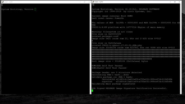
- Power on both controllers within 60 seconds of each other
- Watch the controllers attempt to discover each other during startup
- After both controllers are online, review the HA status by issuing the following commands
- show chassis
- show redundancy
- show romvar
Notes
This section includes some reminders and suggestions.
- In the event of a switchover to the standby, when the active later regains access to the network, or is replaced as a result of a hardware failure, it will not pre-empt the current “active” controller. You must issue the command redundancy force-switchover.
- The standby console is not accessible by default, issue the following commands to enable:
- redundancy
- main-cpu
- standby console enable
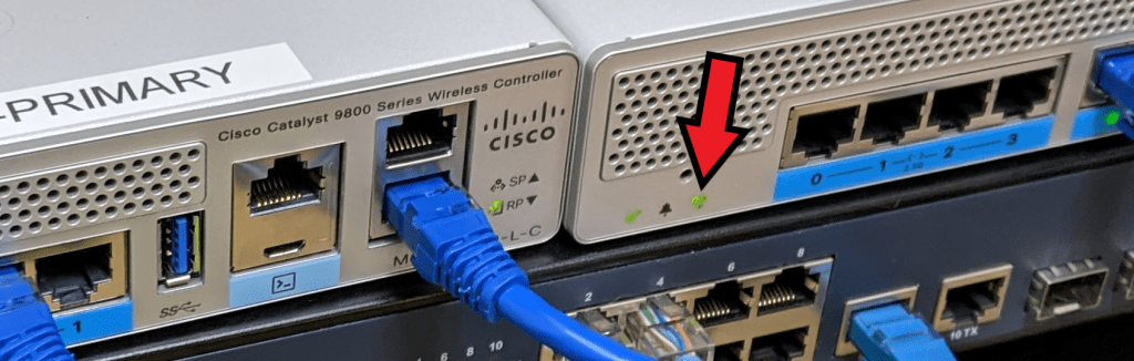
- The HA LED on the front of the controller can be used to identify the “active” peer.
- On: HA active
- Slow blink: HA standby hot
I hope this post has helped you pair up your 9800 controllers quickly with clarity. Stay tuned for more 9800 deployment-related posts!
References
Cisco Catalyst 9800-L Wireless Controller Hardware Installation Guide

Great postings! Direct and with good explanations, i appreciate it.
LikeLike
Thanks !!! Great post and help me a lot.
LikeLike
Finally got my 9800L WLC’s shipped after being on order over a year. I am going through the changes from my 3504’s. It looks like there is a lot to learn, but blogs like yours help a ton.
LikeLike